.jpg.aspx)
Looking at the facade industry today and for the future, there is a progression toward lightweight/low-mass solutions. This is in response to the demand for lowering the amount of embodied energy in the construction industry in an effort to address environmental impact of buildings. Lowering the weight suspended from the building superstructure will also save costs. Over the last decade, more of these solutions are being employed with success, both in function and form. While largely developed in Europe, these solutions have either made the transition to the North American environment seamlessly or with small augmentations in the assembly design. These contemporary and future-friendly facade solutions of both skin and substructure have best practices to follow, and through this, promise good performance with long lifespans.
1 This article addresses the five most common mistakes made in facades as it applies to future-friendly facades.
Mistake #1: Inadequate ventilation
All facade solutions benefit from good ventilation. Yet, the industry continually witnesses systems going up without it. Ventilation has two principle benefits. It helps dry the envelope when there is moisture intrusion, a significant factor affecting the durability of a building envelope. Building moisture can cause mould, corrosion, decay, freeze/thaw damage, and other moisture-related deterioration.
2
Early research in Norway in the 1960s revealed rainscreen systems are effective in managing moisture intrusion. Manufacturers of various systems might claim to be a ‘rainscreen,’ as there are many definitions for it. The one system definition consistently delivering high performance is that of DIN standard 18516,
Cladding for external walls, ventilated at rear – Part 1: Requirements, principles of testing. This particular design is unique as it prescribes a vertical active and uninterrupted cavity. The continual ventilation cavity works with the natural flow of air. Hot air rises, so in the warm months, air naturally in the cavity flows. The cavity is typically 25 mm (1 in.) deep with an opening at the top and bottom. As the air flows through the cavity upward through single or multiple storeys, a vacuum is created. The vacuum is a natural and highly beneficial phenomenon largely due to the stack effect, which conveniently pulls and draws moisture, exhausting it as vapour from the assembly. This method of ventilation is superior to an interrupted system relying on an unnatural horizontal flow.
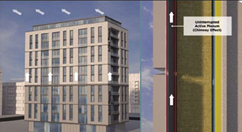 Proper ventilation will keep the envelope dry and exhaust heat energy.
There is also another benefit of this vertical active cavity. It is the ability to exhaust heat energy. In summer, when solar heat gain is bearing down on the facade, energy will naturally radiate inward. In an effort to keep the heat away from the core of the building and raise the interior temperature, it will be exhausted upward, out of the facade assembly and away from the building. The 25-mm active ventilation cavity is, in fact, a microclimate. This benefits insulated and non-insulated envelopes, but for the purpose of this article, the envelope will have some form of continuous outboard insulation. This microclimate is neither the temperature outboard of the cladding nor the temperature within the insulation plane, or the interior of the building.
The microclimate assists in stabilizing temperature fluctuations. It reduces the facade skin thermal stress. It limits solar heat gain from taxing the interior climate.
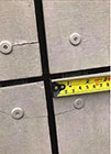 Designing for the coefficient of expansion and contraction will prevent cracking by allowing for movement (floating points) properly located on each panel.
A part of the assembly involves a weather membrane directly in front of the insulation, but behind the 25-mm plenum. This membrane performs the function of a secondary drainage plane. When precipitation enters through the open joint system often found in facades, the weather membrane will prevent the liquid moisture from entering the insulation plane.
These membranes can withstand a head of water. These membranes should ideally be ultraviolet (UV) stable and must be placed directly against the insulation to prevent buffeting, to counteract some of the ill-effects of wind load. If ambient moisture through condensation finds its way into the protected insulation plane, it can be drawn outward through the membrane as vapour through the vacuum created by the upward movement of air in the active plenum. This whole prescription and process helps address and respect the
Ontario Building Code (
OBC) division B Part 5 Environmental Separation and Part 9 of Housing and Small Buildings (particularly A-9.27.2).
To summarize, ventilation through the 25-mm active cavity encourages the envelope to dry. Lastly, there is a thermal benefit from the cavity and microclimate. Engineering firm Morrison Hershfield found through finite analysis exploring a proprietary thermal clip in 2012 the 25-mm cavity offered as much as 0.7 R-value.
Mistake #2: Not designing for the coefficient of expansion and contraction
Facade materials expand and contract. Every building material has a unique value for coefficient of expansion/contraction. A critical design failure is ignoring of these fluctuations in façades and their substructures. Both systems engage in a dynamic dance with one another, and this is largely attributed to changes in temperature and humidity. Over the last 10 years, the author has witnessed façade cracking, warping/oil canning, and fastener failures. As the global climate changes, higher frequencies of extreme weather are placing greater stress on buildings, and, specifically, facades that are at the frontlines 100 per cent of the time.
This all points to designing dynamic building envelopes that can expand and contract with the environmental fluctuations facing it. Facade materials can be hung on a substructure in two ways: exposed or concealed fastening. Both of these methods can address the dynamism required to thwart failure. Proper design and installation of the systems is critical. Taking a look at a typical face fastened (exposed) system, which is less expensive than concealed, fixed and floating points of fasteners are required to hold the facade skin to the substructure. This method ensures the facade skin is held back sufficiently to the substructure, but the nature of the floating points allows the panel to respond to expansion and contraction without locking up and binding. The fixed point(s) positions/locates the panel, where the floating points make up the majority of the fasteners. Floating points are created by over-drilling the fastener hole diameter by only a few millimeters larger than the fastener diameter. The amount of fluctuation is rather small in comparison to the overall size of the facade skin module, but repeated stress between the fasteners and the panel without the float compromises both the facade skin and fastener. This is a very simple and affordable procedure, as well as an empirically proven methodology addressing an unavoidable condition, given the materiality in contemporary facades, typical building practices in North America, and the environmental conditions structures are subjected to. Overtightening of fasteners is a detrimental, easily avoidable issue, and is essentially the equivalent of increasing the number of fixed points and removing float. With the help of available accessories (cordless rivet guns and rivet setting adapters), rivet assemblies have proven to be the easiest to moderate and the most promising for success. Emphasis on cordless rivet guns is key. The use of pneumatic guns and compressors drives the rivets with far too much force and creates overtightening. The use of threaded fastening solutions (screws) is another option to the rivet but it leaves the fastener tension in the hands of the installer and the impact driver. Impact drivers do not have clutches, so the tension is completely arbitrary. This can be disastrous. While many facade skin manufacturers endorse the use of threaded fasteners, the assumption is installation crews will use ‘all means necessary’ to modulate fastening tension so the ideal conditions are met. While this introduces a subjective element, it is this author’s opinion this is an unrealistic and unfair expectation of installers who are usually under time constraints or, in some cases, battling adverse weather conditions of either extreme cold through the winter or heat through the summer.
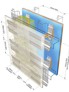 Proper substructure design and installation will extend the lifespan of the facade and give superior results.
Concealed fastening systems inherently have a design allowance for expansion and contraction. They also cost more than exposed fastener systems. At a premium of roughly 30 per cent upcharge (relative supply and installation cost) for concealed systems, the exposed fasteners, with the proper installation methodology, are economical and promise success.
Mistake #3: Substructure design omissions and installation shortcomings
Facade systems are suspended outside of the superstructure. In Canada, the substructure facade skins are typically fastened to are 18-ga galvanized, which is light when compared to structural steel. The challenges faced here are many fold.
As mentioned earlier, a vertical cavity should exist directly behind the panel for good ventilation. Working from the panel back there should be a vertical ‘hat bar’ to support the panel. A horizontal plane of a Z bar, or equivalent will support the hat bar and insulation (assuming there is outboard insulation). In many cases, specific RSI values will be required, thus demanding the implementation of a thermal clip. The clip should be a part of the horizontal member, and best-case scenario would be for the product to be adjustable for sub wall misalignment.
This results in a grid of relative lighter gauge metal (18 ga). One of the principle mistakes made in substructure design and installation occurs at slab edges where the vertical hat bar is extended over traditional points of deflection. It is best to think of it this way. The superstructure is wrapped in a light-gauge steel cage and has traditional points of deflection. The 18-ga net is left to bear the energy/force of this deflection. The outcome is the substructure gets torn apart or buckles, and the facade skin cracks or bows. Vertical members within the substructure must stop and start at each floor slab and respect all other points of deflection in a building. They also require a gap between each other. This has been witnessed where lengths of vertical members—up to 8 m (25 ft) long—are stitched together with fasteners to climb the height of a building and cross over every floor slab. Too many times a lightweight facade skin will fall victim to this condition, crack or bow, and the skin material is assumed to be the issue. When cracks occur in masonry walls, one assumes the building settled or shifted, and the blame is directed toward the ‘settling of the structure,’ and not necessarily the masonry. Lightweight façade systems are also at the mercy of this settling, shifting, and deflection phenomenon, and can experience failure just like masonry. However, these are often characterized as a ‘material failures’. Lightweight facade systems can manage the movement with ease when the proper principles are adopted and implemented.
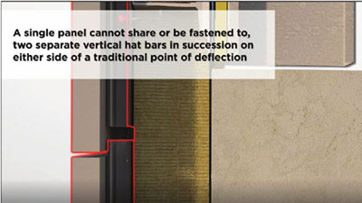 Hat bar must stop and start at traditional points of deflection.
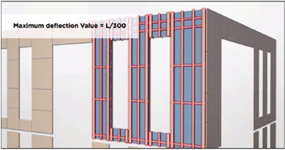 Facade systems should be engineered for a deflection limit of L/300.
Another item to consider is when vertical members have joints, a singular façade panel should never cross the gap when being fastened to separate vertical girts in succession. As the substructure expands, contracts, and responds to the points of deflection, girts move independently and not always in the same direction or at the same rate. The panel modules should stop and start as the vertical members supporting them do. This principle also applies to expansion joints, though specific superstructure expansion joints will require a detail for far greater movement. Horizontal members in the insulation plane cannot be continuous either. A gap should be present when these members stop and start in succession. While movement along the horizontal members is not as common, notwithstanding expansion and contraction, they need to respect these basic principles as well. Girts, regardless of their configuration ( Z, hat, exterior/interior corner) can all be ordered in various sizes to suit the specific project, and this can be determined during the shop drawing phase.
As discussed in the previous section, the opportunity for expansion and contraction of all components in the façade system is always present and when married with the traditional points of deflection in a superstructure, the big picture is quite dynamic. Designing and assembling a high performance substructure is not difficult, but the outcome of a poorly designed and installed one is.
Mistake #4 – Poor deflection limit of substructure
In the author’s experience, substructures for lightweight façade systems should be engineered for a deflection limit of L/300. Girts and panels expand and contract. The superstructure will exercise some deflection, and in some cases/places, take the substructure with it. However, the substructure should not be experiencing an out-of-plane deflection of more than L/300.
Typical façade skin materials, such as panels of porcelain, high-density fibre cement, phenolic, ceramic/terra cotta, promise great performance and longevity when designed and installed correctly. When a substructure has more deflection in out-of-plane conditions, it will place unnecessary stress on panels and the fastening system, resulting in panel cracking and distortion. For many Canadian scenarios, designing a substructure with 18-ga girt systems is a great start to achieving a limit of L/300. Spans between the members and the respective fastening points will play a large role in determining this deflection limit, but there are other key factors as well. For example, ‘hat bars’ are being used for the vertical members directly behind the panels. These are sometimes called ‘omega’ channels. Hat bars, due to their shape, have higher deflection resistance than a Z bar of the same size and gauge.
Designing a substructure that suits the products fastened to it and engineered to confront the dynamic conditions surrounding it of not only today, but tomorrow will give the ‘frontline systems’, the advantage they require to deliver the required performance.
Mistake #5 – Inadequate shop drawings
Shop drawings are instructions for installation of a specific project. Instead of being specific and comprehensive, inadequate drawings merely show a few of the basic details of the project’s general conditions. An ideal shop drawing package will determine a successful path for installation.
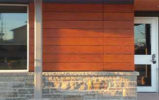 The Collingwood Firehall in Ontario features a wood veneer façade used with rivets whereby one of four exposed fasteners are fixed and the other three are floating points to allow for the coefficient of expansion and contraction. Project team includes MCL Architects and GRC Contracting.
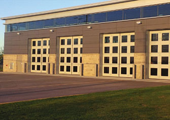 In the Collingwood Firehall project, superior shop drawings clearly outlined that no two panels would be fastened to two girts in vertical succession.
It will present a ‘system drawing’ that could be a few pages long depending on the project’s complexity, and illustrate the fundamental principles of fastener spacing, ventilation cavity in sections and plan view, and the substructure assembly for quick reference at any time during the façade installation. The shop drawings should also detail the fixed and floating points of fasteners (for exposed fastener conditions) as well as the components and placement of concealed fastener systems when applicable. An elevation view of substructure layout is also common. Concluding the shop drawings should be general notes itemizing in detail all the components going into the façade assembly (fasteners, girts, membranes, panel manufacturer and makeup, etc.). The main body of the shop drawings will present elevation views of all applicable areas for installation of the façade and a comprehensive panel layout. Details in section view will be provided showing how the façade system assimilates with windows, flashings, adjacent materials, roof, exterior/interior corner conditions, horizontal/vertical joints between façade skin, and expansion joints in superstructure.
While the content of shop drawings is plentiful, and the time and effort to complete them is significant, the value is unquestionable. Everyone including designers, constructors, and end-users benefit from complete, high-quality shop drawings. The complexity of construction has increased in recent times to embrace more sophisticated assemblies with higher thermal performances to address the challenging effects of climate change. With this added complexity and the need for more resilient structures, it seems logical to eliminate the unnecessary variables (
e.g. shop drawings) diminishing the quality of façades.
Conclusion
Mistakes cost money is the old adage. In this case, some of these issues are not unanimously outright mistakes, but oversights or honest ignorance of best practices. The good news is these issues are completely preventable and getting project teams on the high road of design is readily achievable.
Notes
1 Future friendly refers to lower embodied energy solutions to minimize carbon footprint and provide superior thermal performance to address the more demanding building code requirements.
2 Visit energyeducation.ca.
 Jeff Ker has more than eight years of technical sales experience in the Ontario architectural and design industry. His experience includes two years in the West Coast market and more than six years in the Eastern Canadian market, representing a variety of rear-ventilated rainscreen (RVRS) systems. Ker has a solid background in technical sales, project management, and liaison with the construction community. He can be reached via e-mail at jker@engineeredassemblies.com.
To view the full article in Construction Canada click here:
https://www.constructioncanada.net/publications/de/202006/